
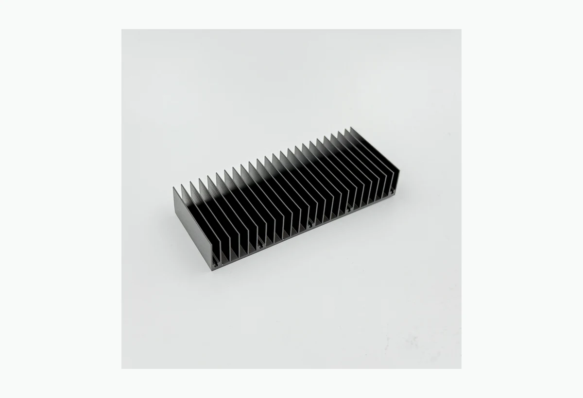
A blanket tight tolerance rarely improves an audio product. It usually increases setups, inspection, cycle time, and rejection risk. Better drawings identify the interfaces that control fit, heat flow, alignment, sealing, or appearance and allow practical manufacturing tolerance elsewhere.
01
Build tolerance from function and datum
Start with how the part locates in the assembly. A heat sink may use one primary mounting plane, a PCB or device interface, and connector or fastener patterns. A bracket may depend on hole position to a cabinet datum. A knob may depend on bore fit and indicator orientation. These relationships should drive the datum scheme.
When dimensions are chained without a functional datum, variation accumulates and inspection becomes difficult to interpret. Coordinate or position controls tied to assembly datums often communicate intent more clearly than many independent plus-minus dimensions.
- Choose assembly datums first
- Control relationships, not isolated dimensions
- Avoid redundant or conflicting dimensions
02
Recognize the features that drive cost
Deep pockets, thin walls, long slender features, small internal radii, tight bores, large flat surfaces, and dimensions spanning multiple setups can require slower cutting, special tools, stress management, or additional inspection. Cosmetic surfaces may need separate handling even when their dimensions are simple.
Anodizing, blasting, polishing, and coating occur after machining and can influence size, thread behavior, contact, and appearance. Drawings should identify mask zones and whether dimensions apply before or after finish. Otherwise suppliers may quote different assumptions.
- Mark post-finish requirements
- Review tool access and internal radii
- Separate cosmetic and dimensional acceptance
03
Use process capability as a discussion, not a website number
Achievable tolerance depends on part size, geometry, material condition, setup, machine, feature type, inspection method, and batch strategy. A supplier can hold a demanding local feature on one part while a broad statement about every dimension would be misleading.
For quotation, classify features as critical, assembly, cosmetic, or reference. Ask the supplier to identify the dimensions that require special control and the proposed inspection method. This creates a more useful capability conversation than asking for one general tolerance value.
- Flag safety and fit-critical features
- Agree inspection method before production
- Use general tolerance for non-critical geometry
04
Control first article and repeat production
The first article should confirm the manufacturing datum strategy, critical dimensions, threads, finish interfaces, and trial assembly where available. It should also expose drawing ambiguities before repeat batches begin.
For production, the control plan can combine setup verification, in-process gauges, periodic dimensional checks, visual standards, and final sampling. The level of documentation should match part risk and purchase requirements rather than adding paperwork with no decision value.
- First-article report for agreed characteristics
- Thread and fit gauges where practical
- Revision and approved-deviation control
RFQ
Information to send with the drawing
- STEP model plus controlled 2D drawing
- Critical dimensions and datum references
- Mating parts or assembly description
- Material temper and finish
- Prototype and annual quantities
Engineering responsibility
This guide describes manufacturing considerations, not a product certification or universal specification. Acoustic, structural, thermal, electrical, safety, and regulatory validation remain project-specific and must be approved by the responsible product team.