
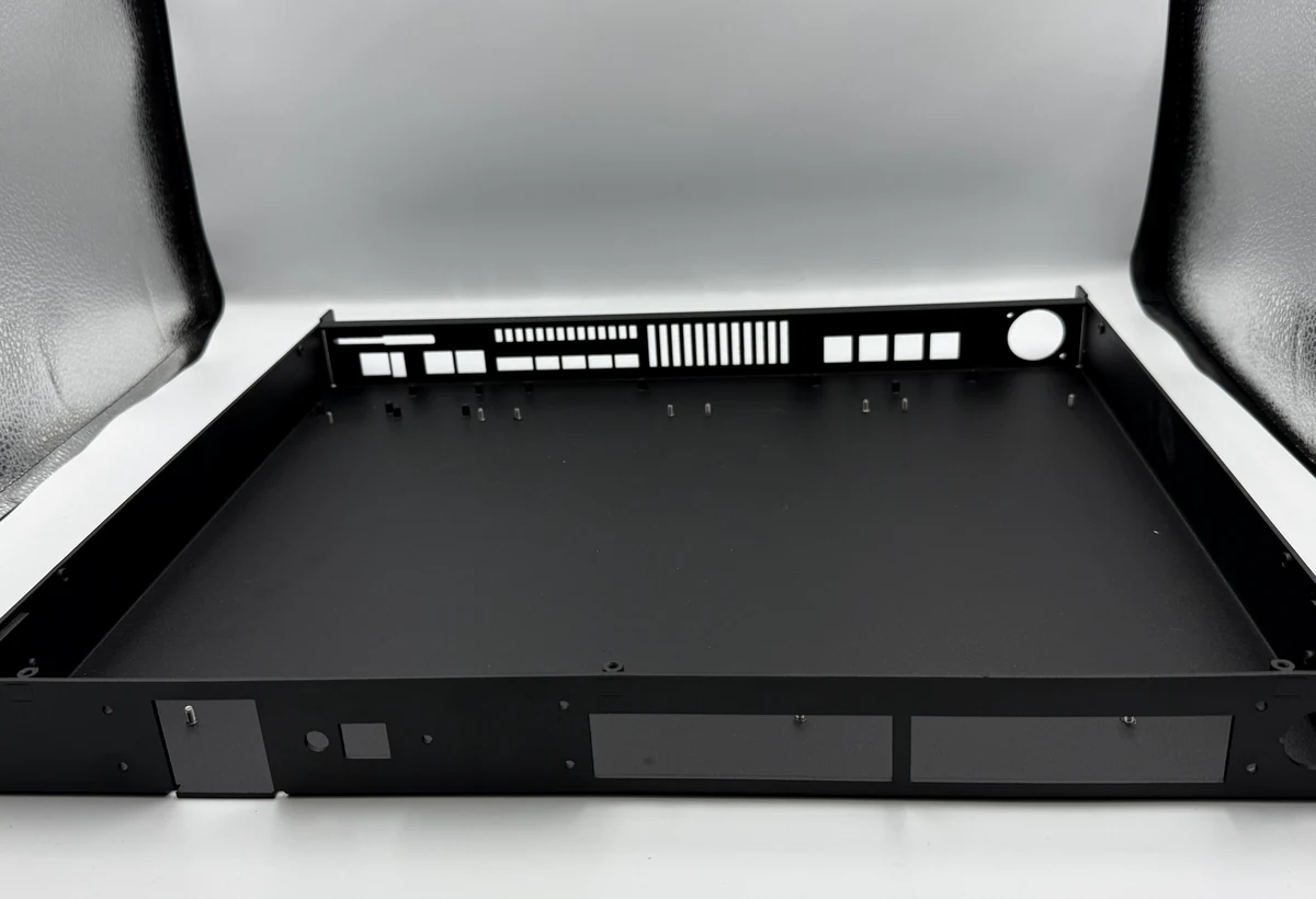
An amplifier chassis is a structural frame, thermal path, electrical enclosure, user interface, and assembly platform. Decisions about sheet metal, heat sinks, ventilation, grounding, connector positions, service access, and finish should be reviewed as one system before drawings are released.
01
Define the mechanical and electrical architecture
Begin with PCB, power device, transformer, fan, connector, display, and cable locations. Identify which surfaces establish board position, which joints provide shielding or grounding, and which panels must be removable for service. This prevents late conflicts between electronics and fabrication.
A chassis assembled from several bent parts can be economical and serviceable, while an extrusion or machined housing can combine thermal and cosmetic functions. Hybrid construction is common: sheet metal internal structure with a machined heat sink or faceplate.
- Define board and connector datums
- Map service and tool access
- Identify grounding and shielding contacts
02
Design the thermal path before cosmetic finish
Power devices need controlled contact to a heat spreader or heat sink. Flatness, interface material, mounting pressure, fastener sequence, and coating masks may matter more than the appearance of the surrounding surface. Vent patterns and fan paths must also account for internal obstructions.
Anodizing and paint may be desirable externally but can interfere with electrical or thermal contact. Drawings should identify bare, masked, or conductive interfaces and define how those areas are protected during handling and assembly.
- Mark thermal contact zones
- Define mask boundaries
- Review airflow in the assembled product
03
Make sheet metal tolerant of real assembly
Bend relief, inside radius, hardware clearance, weld sequence, and tolerance stack determine whether panels align without forcing. Captive nuts or self-clinching hardware can improve assembly, but edge distance and insertion access must be designed correctly.
Connector cutouts should use the supplier drawing for the actual component and include access for mating plugs and locking features. Cable bend radius, strain relief, and harness routing are often missed when only the front view is reviewed.
- Check formed-part tolerance stack
- Validate all connector keep-out zones
- Plan captive hardware and assembly sequence
04
Release with fit, finish, and function evidence
A first assembly is more informative than isolated dimensional reports. It can reveal connector misalignment, panel gaps, screw access, grounding contact, cable interference, heat sink seating, and cosmetic damage during assembly.
Production control may include key dimensions, thread and insert checks, finish appearance, mask zones, trial assembly, labels, and protective packing. Electrical safety, EMC, and thermal performance remain the responsibility of the product validation program.
- First article with trial assembly
- Approved appearance and label sample
- Separate manufacturing checks from product compliance tests
RFQ
Information to send with the drawing
- 3D assembly and 2D part drawings
- PCB, connector, and heat-source layout
- Thermal, grounding, and masking requirements
- Finish and cosmetic zones
- Assembly, labeling, testing, and packing scope
Engineering responsibility
This guide describes manufacturing considerations, not a product certification or universal specification. Acoustic, structural, thermal, electrical, safety, and regulatory validation remain project-specific and must be approved by the responsible product team.