
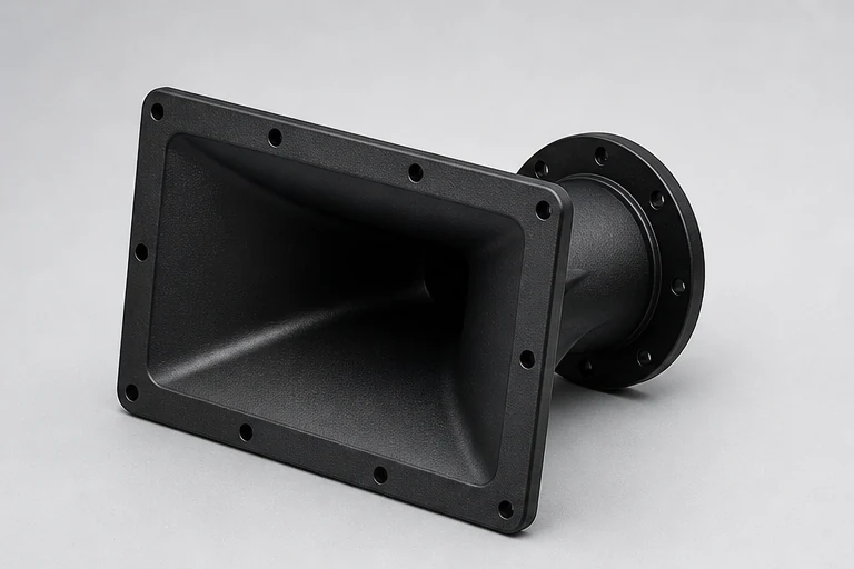
A waveguide is both an acoustic device and a manufactured component. The production route must preserve the surfaces that control directivity while also providing draft, wall structure, fastening, finish, and repeatable inspection. Treating it as ordinary cosmetic plastic usually creates avoidable tooling or assembly problems.
01
Separate acoustic geometry from supporting geometry
The throat transition, flare profile, mouth boundary, and relationship to the compression driver are usually the surfaces that deserve the tightest design control. Mounting flanges, hidden ribs, bosses, and rear supports can often be adjusted for manufacturing without changing acoustic intent, provided the design team identifies that freedom before DFM begins.
A useful drawing distinguishes acoustic surfaces, sealing surfaces, driver datums, cabinet interfaces, cosmetic zones, and non-critical structure. This gives the toolmaker room to solve shrinkage, ejection, cooling, and stiffness while protecting what the acoustic simulation and listening tests actually depend on.
- Mark driver and cabinet datums
- Identify no-change acoustic surfaces
- Define gasket compression and fastener access
02
Prototype the question you need to answer
CNC machining is useful when the priority is acoustic geometry, driver alignment, or fast iteration without mold tooling. Additive manufacturing can be useful for form and assembly checks, but material stiffness and surface texture may differ from production. A prototype plan should state whether the sample is for acoustic test, packaging, appearance, or assembly.
Before moving to a mold, compare the validated prototype with the molded design. Draft, radii, wall transitions, parting line, gate position, and texture can all alter the final surface. The production CAD revision should be re-reviewed rather than assuming that a successful machined prototype automatically guarantees a successful molded part.
- CNC for geometry-led acoustic tests
- Printed samples for packaging and fit
- Revalidate the production CAD after DFM
03
Design the mold around visible and acoustic surfaces
Parting lines and ejector marks should be kept away from critical acoustic transitions and visible front surfaces where practical. Gate location affects weld lines, pressure, appearance, and dimensional stability. Thick-to-thin transitions can create sink or uneven shrinkage, while insufficient draft can damage texture during ejection.
Material choice changes the DFM discussion. ABS offers practical processing and appearance; PC/ABS can improve impact performance; glass-filled PA can add stiffness but may influence surface, shrinkage, and dimensional behavior. Resin should be chosen from acoustic, structural, environmental, cosmetic, and production needs together.
- Agree parting, gate, and ejector zones
- Review wall and rib ratios
- Confirm texture with draft and resin
04
Inspect what protects sound and assembly
Inspection should follow the part function. Throat and driver interfaces, mounting patterns, flange flatness, cabinet fit, and critical profile checks normally matter more than applying tight tolerances to every dimension. A profile fixture, CMM strategy, scan comparison, or section gauges may be appropriate depending on geometry and risk.
The production standard should also cover flash, short shot, sink, color, texture, contamination, and packing protection. Approved samples and a clear change record help acoustic, purchasing, and supplier teams avoid judging each batch from memory.
- Critical interface report
- Approved appearance sample
- Fit and acoustic validation owned by the product team
RFQ
Information to send with the drawing
- 3D STEP model and controlled 2D drawing
- Driver and cabinet mating information
- Prototype purpose and annual quantity
- Resin, texture, color, and environmental target
- Critical acoustic and assembly surfaces
Engineering responsibility
This guide describes manufacturing considerations, not a product certification or universal specification. Acoustic, structural, thermal, electrical, safety, and regulatory validation remain project-specific and must be approved by the responsible product team.